Breslaujos st. 3
Kaunas, Lithuania
 Heating equipment
 Ventilation equipment
 Cooling equipment
 Fan water heaters
 Gas heaters
 Air curtains
 Hot water
 Ambient
 Gas fired
 Fan coils
 Wall mounted
 Concealed
 External gas heaters
 Infrared heaters
 Electric
 Gas - radiant tube
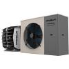 Heat pumps
 Gas
Gas Destratification fans
 Gas radiators
 Gas boilers
 Electric heaters
 Diesel fired heaters
 Containers and drums heating
 IBC containers heaters
 Drum heaters
 Gas cylinders heaters
 Heating blankets and mats
 Ventilation components
 Anemostat diffusers
 Air grilles
 Wall grilles
 Air-flow grilles
 Floor air grilles
  Doors air grilles
 Spiral grilles
 Egg crate grille
 Pressed air grilles
 Metal-mesh air grilles
 Perforated air grilles
 Low-velocity diffusers
 Louvre systems / Regulating louvres
 External intake louvres
 External exhaust louvres
 Roof units
 Intake & Exhaust louvres
 Roof bases
  Cylindrical roof exhaust
  Under-window air valves
 Plenum box
 Dampers
  Duct dampers
  For grilles & diffusers
 Fans
Fans Roof mounted extraction fans
 Wall mounted extraction fans
 Smoke extraction fans
 Ducted fans
 Evaporative air coolers
 Dry coolers
 Remote condensers
Water air curtain - ELiS G-W-250 3V | Flowair
Select the product model:


Water air curtain, industrial, horizontal and vertical mounting, copper heat exchanger with aluminum plates, heating capacity: from 13.7 kW (50/40°C) to 43.6 kW (90/70°C), high air flow: three speeds 4300/7200/12000 m³/h, FLOWAIR axial fans, total fans power 1400 W, length 2.5 m, max. mounting height 7.5 m, 2 year WARRANTY
Manufacturer:


Interested in this product? Contact us:
+370 601 74426

Sales representative for Vilnius, Ukmergė, Utena, Kaišiadorys and Varėna regions Get Offer
+370 606 11865

Sales representative for Kaunas, Panevėžys, Šiauliai, Telšiai, Klaipėda, Tauragė, Marijampolė and Alytus districts Get Offer
Arvydas Palivonas
LT, RU, EN+370 601 74426
Sales representative for Vilnius, Ukmergė, Utena, Kaišiadorys and Varėna regions Get Offer
Andrius Lekarevičius
LT, RU, EN+370 606 11865
Sales representative for Kaunas, Panevėžys, Šiauliai, Telšiai, Klaipėda, Tauragė, Marijampolė and Alytus districts Get Offer
Model:
ELiS G-W-250 3V
General data
Heating capacity at 90/70°C water and 10°C air temperature, fan at max speed
kW
43,6
Heating capacity at 50/40°C water and 10°C air temperature, fan at min speed
kW
13,7
Air temperature rise (ΔT) at 90/70°C water and at 10°C air temperature
°C
10,5
Max. air flow
m³/h
12000
Fan data
Power supply
V/Hz
1N ~ 230/50
Fan type
AC
IP / Insulation class
54
Steps
3
Fan data at 3rd (max) speed
Air flow
m³/h
12000
Power consumption
W
1400
Current consumption
A
6,0
Acoustic pressure level at a distance of 5 m from the unit, in the 1500 m³ room of medium capabillity of sound absorption
dB(A)
69
Fan data at 2nd (mid) speed
Air flow
m³/h
7200
Power consumption
W
970
Current consumption
A
4,8
Acoustic pressure level at a distance of 5 m from the unit, in the 1500 m³ room of medium capabillity of sound absorption
dB(A)
58
Fan data at 1st (min) speed
Air flow
m³/h
4300
Power consumption
W
490
Current consumption
A
2,5
Acoustic pressure level at a distance of 5 m from the unit, in the 1500 m³ room of medium capabillity of sound absorption
dB(A)
47
Installation data
Max. heating water temperature
°C
120
Max. operating pressure
MPa
1,6
Hydraulic connection
Ø "
¾
Max. mounting height
m
7,5
Max. width of door with curtain on one side
m
7,5
Min. fan distance to the wall
m
0,4
Max. door width with curtain on both sides
m
13
Min. distance to ceiling
m
0,4
Dimensions
Length
mm
2582
Depth
mm
550
Height
mm
650
Weight without water
kg
78,3
Dimensions
Model:
ELiS G-W-250 3V

Heating capacity tables
ELiS G-W-250 3V airflow on 3 speed = 12000 m³/h
Tp1
°C
PT
Qw
∆pw
Tp2
kW
l/h
kPa
°C
0
5
10
15
20
Tw1/Tw2 = 110/90°C
63,0
2806
28,0
15,5
60,1
2677
25,7
19,5
57,2
2546
23,4
24,0
54,1
2407
21,1
28,0
50,9
2263
18,8
32,5
0
5
10
15
20
Tw1/Tw2 = 90/70°C
49,6
2191
18,6
12,0
46,7
2061
16,6
16,5
43,6
1926
14,7
20,5
40,6
1792
12,9
25,0
37,3
1647
11,0
29,0
0
5
10
15
20
Tw1/Tw2 = 80/60°C
43,0
1889
14,5
10,5
40,0
1756
12,7
14,5
36,9
1621
11,0
19,0
33,8
1486
9,3
23,0
30,5
1341
7,7
27,5
0
5
10
15
20
Tw1/Tw2 = 70/50°C
36,2
1586
10,8
9,0
33,2
1453
9,2
13,0
30,1
1316
7,7
17,5
26,9
1179
6,3
21,5
23,6
1035
5,0
26,0
0
5
10
15
20
Tw1/Tw2 = 60/40°C
29,4
1284
7,6
7,0
26,3
1149
6,2
11,5
23,2
1011
4,9
15,5
19,9
870
3,7
20,0
16,6
724
2,7
24,0
0
5
10
15
20
Tw1/Tw2 = 50/40°C
27,6
2404
24,4
6,5
24,5
2135
19,6
11,0
21,4
1864
15,3
15,0
18,2
1587
11,4
19,5
15,0
1304
7,9
23,5
ELiS G-W-250 3V airflow on 2 speed = 7200 m³/h
Tp1
°C
PT
Qw
∆pw
Tp2
kW
l/h
kPa
°C
0
5
10
15
20
Tw1/Tw2 = 110/90°C
50,8
2261
18,8
20,5
48,5
2158
17,3
24,5
46,1
2052
15,7
28,5
43,5
1938
14,1
32,5
40,9
1821
12,6
36,5
0
5
10
15
20
Tw1/Tw2 = 90/70°C
40,1
1768
12,5
16,5
37,7
1662
11,2
20,5
35,2
1554
9,9
24,5
32,7
1443
8,6
28,5
30,1
1327
7,4
32,0
0
5
10
15
20
Tw1/Tw2 = 80/60°C
34,7
1523
9,8
14,0
32,2
1417
8,6
18,0
29,7
1308
7,4
22,0
27,3
1198
6,3
26,0
24,6
1081
5,2
30,0
0
5
10
15
20
Tw1/Tw2 = 70/50°C
29,2
1280
7,3
12,0
26,8
1172
6,2
16,0
24,3
1062
5,2
20,0
21,7
952
4,2
24,0
19,1
836
3,3
28,0
0
5
10
15
20
Tw1/Tw2 = 60/40°C
23,8
1037
5,1
9,5
21,3
927
4,2
13,5
18,7
816
3,3
17,5
16,1
702
2,5
21,5
13,4
584
1,8
25,5
0
5
10
15
20
Tw1/Tw2 = 50/40°C
22,2
1937
16,4
9,0
19,8
1721
13,2
13,0
17,2
1501
10,3
17,0
14,7
1278
7,6
21,0
12,1
1050
5,3
25,0
ELiS G-W-250 3V airflow on 1 speed = 4300 m³/h
Tp1
°C
PT
Qw
∆pw
Tp2
kW
l/h
kPa
°C
0
5
10
15
20
Tw1/Tw2 = 110/90°C
40,4
1799
12,3
27,5
38,6
1717
11,3
31,5
36,6
1628
10,3
35,0
34,5
1537
9,2
38,5
32,5
1445
8,2
42,0
0
5
10
15
20
Tw1/Tw2 = 90/70°C
31,9
1407
8,2
21,5
30,0
1323
7,4
25,5
28,0
1236
6,5
29,0
26,0
1146
5,7
32,5
23,9
1055
4,9
36,5
0
5
10
15
20
Tw1/Tw2 = 80/60°C
27,6
1213
6,4
19,0
25,7
1128
5,6
22,5
23,7
1041
4,9
26,0
21,6
952
4,1
29,5
19,6
860
3,4
33,5
0
5
10
15
20
Tw1/Tw2 = 70/50°C
23,3
1019
4,8
16,0
21,3
933
4,1
19,5
19,3
847
3,4
23,0
17,3
757
2,8
27,0
15,2
665
2,2
30,5
0
5
10
15
20
Tw1/Tw2 = 60/40°C
18,9
825
3,4
13,0
16,9
738
2,8
16,5
14,9
650
2,2
20,0
12,8
559
1,7
23,5
10,7
464
1,2
27,0
0
5
10
15
20
Tw1/Tw2 = 50/40°C
17,7
1537
10,7
12,0
15,7
1366
8,6
15,5
13,7
1192
6,7
19,5
11,7
1016
5,0
23,0
9,6
834
3,5
26,5
- PT - heating capacity
- Tp1 - air temperature at the unit inlet
- Tp2 - air temperature at the unit outlet
- Tw1 - heating medium temperature at the heat exchanger inlet
- Tw2 - heating medium temperature at the heat exchanger outlet
- Qw - heating medium flow rate in heat exchanger
- Δpw - heating medium pressure drop in heat exchanger


-1200x0-s.jpg)
-1200x0-s.jpg)
-1200x0-s.jpg)
-1200x0-s.jpg)
-1200x0-s.jpg)
-1200x0-s.jpg)
-1200x0-s.jpg)
-1200x0-s.jpg)
-1200x0-s.jpg)
-1200x0-s.jpg)